


Standards-led guidance on Type C FIBC earthing, resistance verification and why lower-limit object recognition can create false confidence.
Type C FIBC earthing systems monitor the upper resistance threshold because the relevant standards define the maximum resistance needed for safe charge dissipation. Adding a lower resistance limit can add circuit complexity and does not reliably prove that the connected object is the intended Type C FIBC.
Reliable electrostatic earthing is key to safe hazardous area operations using Type C FIBCs. The reliability of this connection to earth includes an upper resistance limit in order to allow the safe dissipation of charge, as reflected in the relevant national and international safety standards.
However, while these standards provide guidance on an upper resistance limit, it may appear to be even safer to include a lower resistance limit as well, so that the correct object can be identified and to prevent attempts to bypass or manipulate the system.
Why Type C FIBC earthing uses an upper threshold only
This article examines the recommended practice to establish an electrostatic earthing connection for Type C FIBCs to an upper resistance threshold for confirmation of the connection to a verified earthing point on site, and why the addition of a lower resistance threshold may not be quite as beneficial as it appears.
Upper limit is defined
IEC 61340-4-4 and NFPA 77 align around a maximum Type C FIBC resistance threshold of 1 × 10⁸ Ω.
Connection is verified
Active earthing confirms the safe connection to the verified site earthing point and can signal if the connection is interrupted.
Training still matters
Automatic monitoring supports competent operators and safe procedures; it should not be treated as a substitute for them.
Which standards define the Type C FIBC earthing resistance limit?
The answer to the first part lies in the standards and industry best practice for hazardous area FIBC operations. Firstly, particularly for operators in Europe, the ATEX workplace safety directive sets out a requirement to prevent the ignition of an explosive atmosphere, including preventing ignition sources such as electrostatic sparks.1
A more specific requirement for FIBC earthing is set out in the International Electrotechnical Commission’s guidance with IEC TS 60079-32-1, which states that “Type C FIBC are designed to be connected to earth during filling and emptying operations”.2
As to the nature of this electrostatic earthing connection, the international standard IEC 61340-4-4 and American recommended practice NFPA 773 agree that a Type C FIBC used for transfer operations in flammable or explosive atmospheres “shall have a resistance to groundable point of less than 1 × 10⁸ Ω”.4 The international standard has then in turn been adopted in a number of national standards, including the British BS EN IEC 61340-4-45 and German DIN EN IEC 61340-4-4.6
| Reference | Relevance for Type C FIBC earthing |
|---|---|
| ATEX workplace safety directive | Requires prevention of ignition sources in explosive atmospheres, including electrostatic sparks. |
| IEC TS 60079-32-1 | States that Type C FIBCs are designed to be connected to earth during filling and emptying operations. |
| IEC 61340-4-4 / BS EN IEC 61340-4-4 | Defines the Type C FIBC resistance requirement used to support controlled dissipation of charge. |
| NFPA 77 | American recommended practice aligned around the same upper resistance concept for Type C FIBC operations. |
Annex F of the IEC 61340-4-4 provides further detail on the reasoning behind this upper limit,7 which is based on research undertaken by Yamaguma et al, and reaches the conclusion that “a heavy-duty Type C FIBC of slightly less than 1 × 10⁸ Ω is quite unlikely” to become an ignition source even when exposed to an “unrealistically large static current of 30 μA,” as long as it is suitably earthed.8
A heavy-duty Type C FIBC of slightly less than 1 × 10⁸ Ω is quite unlikely.
Yamaguma et al., as cited in IEC 61340-4-4 Annex FIn short, even when subjecting the bag to a higher electrostatic streaming current that could realistically be expected during normal transfer operations, the tested Type C FIBCs stubbornly refused to act as an ignition source when provided with a connection to earth of slightly less than 1.0 × 10⁸ Ω.
There are numerous advantages to working with this upper resistance threshold as the foundation of an active electrostatic earthing solution. In addition to significantly reducing the risk of fire or dust explosion during operation, using an active electrostatic earthing solution allows operators to monitor the safe connection to the site’s verified earthing point with visual indication of a good connection, provide indication if this connection is interrupted, and allow for interlocks with process equipment to automatically shut off if the connection is disrupted.
It is important to note at this point that while the standards and the research on which they are based are clear on this upper resistance threshold, there is no mention of a lower resistance threshold at the other end of the scale.
Why do Type C FIBC earthing systems not need a lower resistance limit?
As far as the standards are concerned, the resistance of a Type C FIBC to earth can be 1.0 × 10⁸ Ω, 100 Ω, or 1 Ω, and the way the earthing connection works would remain unchanged. The addition of a lower resistance threshold ipso facto adds additional complexity to the monitoring circuit, which provides additional possible points of failure or inconsistency in operation. In exchange for this added complexity, it can be posited that where lower resistance limits are put forward, the proposed benefit can be less in terms of conforming to the standards and best practice, and more as a form of object recognition, attempting to make the system foolproof, or allowing the system to be used in place of trained or competent operators. Each of these possible benefits can be examined in turn.
Can lower-limit monitoring reliably identify a Type C FIBC?
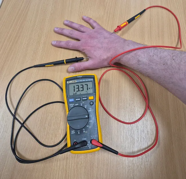
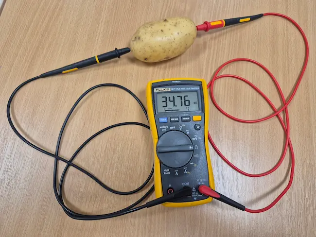
For object recognition, the proposition is that an operator may – by mistake or intentionally trying to bypass the system – connect an earthing clamp to an object other than a Type C FIBC. If that object is not conductive, such as a block of wood or article of clothing, its resistance will be higher than the monitored upper limit and the system will not go permissive. If the object is conductive, such as a metal tool or guardrail, the resistance will be lower than the monitored lower limit and the system will not go permissive. Therefore, the proposition goes, only a correct connection to a Type C FIBC will allow the system to go permissive.
This distinction makes intuitive sense but overlooks a crucial detail that other objects are able to fit within a window of permissible resistance of, for example, 100 Ω - 1 × 10⁸ Ω, but are in fact not Type C FIBCs.
This not only calls the role of object recognition into question when used with a known Type C FIBC but also raises the possibility of a false positive if the system can be made to give a permissive signal when connecting to an object other than the intended bag.
Does a lower resistance limit make Type C FIBC earthing foolproof?
This plays into the second assumption, that object recognition provided by a lower resistance limit can make a system foolproof or impossible to manipulate. To quote Douglas Adams, a common mistake that people make when trying to design something completely foolproof is to underestimate the ingenuity of complete fools.9 As the list of items which fall within the resistance window includes the human body, a sufficiently determined operator has at their disposal the means to quite literally manipulate10 such a system by deciding to remove a glove.
Can object recognition replace operator training and SOPs?
This then leads us to the third assumption, that a system with automatic object recognition by means of an upper and lower resistance threshold can be used as a substitute for operator training or competence.
As with the previous issues, if a system can be fooled by a sufficiently determined person deliberately acting in bad faith or accidentally through lack of understanding, a solution which simply raises higher barriers without addressing underlying safe operating procedures may encourage bad actors to regroup and try again or operators without the necessary training or competence to roll the dice again for another unintended outcome.
Instead, the purpose of an earthing solution which monitors to the recommended upper resistance level only is to support trained and competent operators in carrying out their work safely.
This can include acting as an automatic check that the standard operating procedure is in alignment with the relevant standards, a prompt to help ensure that safe standard operating procedure is followed by having the system’s “Go” signal as part of an operational checklist, and providing an automatic notification or shutoff response in the event that the connection is accidentally disrupted during operation.
Want to verify your Type C FIBC earthing method?
Request a live demo to see how verified earthing, GO/NO-GO indication, and process interlocks can support your operation.
Upper-threshold monitoring supports safer Type C FIBC earthing
What conclusions may be drawn from this?
On the one hand, it has been demonstrated that the use of an upper resistance threshold for Type C FIBC earthing connections carries a number of key benefits, including the safe dissipation of electrostatic charge mitigating the risk of the formation of an incendive spark in hazardous area operations, conformance to the relevant standards and industry best practice, and supporting safe working procedures to be carried out by trained and competent operators.
On the other hand, the use of a lower resistance threshold comes with significant drawbacks. In addition to the increased complexity of the monitoring circuit forming an open invitation to Murphy’s law, the use of this permissive window to act as object recognition has some important limits to what can be recognised as a permissible object. The attempt to make a system foolproof and impossible to manipulate can still leave it open to being fooled and manipulated, and false positives can add another area of uncertainty. Finally, an automated system alone is no replacement for operators’ training and competence or safe standard operating procedure.
Type C FIBC earthing FAQs
What is a Type C FIBC?
Why do Type C FIBCs need to be earthed?
How can a Type C FIBC be safely earthed?
What do the standards and guidance documents say about Type C FIBC earthing?
What is the maximum resistance threshold for Type C FIBC earthing?
Need application-specific support?
Contact Newson Gale to discuss Type C FIBC earthing, resistance monitoring and equipment selection for your process.
Footnotes and sources
Footnotes are listed so each superscript number in the article links to the supporting reference.
Footnotes
- Directive 1999/92/EC of the European Parliament and of the Council of 16 December 1999 on minimum requirements for improving the safety and health protection of workers potentially at risk from explosive atmospheres, Article 3. Back ↑
- IEC Technical Specification 60079-32-1 Explosive atmospheres - Part 32-1: Electrostatic hazards, guidance § 9.6.1. Back ↑
- NFPA 77 (2024) Recommended Practice on Static Electricity. Back ↑
- IEC 61340-4-4:2018 Electrostatics - Part 4-4: Standard test methods for specific applications - Electrostatic classification of flexible intermediate bulk containers (FIBC) § 7.3.1. Back ↑
- BS EN IEC 61340-4-4:2018 - TC Electrostatics - Standard test methods for specific applications. Electrostatic classification of flexible intermediate bulk containers (FIBC). Back ↑
- DIN EN IEC 61340-4-4:2019-01, VDE 0300-4-4:2019-01, Elektrostatik - Teil 4-4: Standard-Prüfverfahren für spezielle Anwendungen - Einordnung flexibler Schüttgutbehälter (FIBC) in elektrostatischer Hinsicht (IEC 61340-4-4:2018); Deutsche Fassung EN IEC 61340-4-4:2018. Back ↑
- IEC 61340-4-4, op. cit., Annex F. Back ↑
- Yamaguma, M., Goto, K., Kokubun, A., A study on resistance of anti-electrostatic flexible intermediate bulk containers, J. Chem. Eng. Jap. Vol. 8 No. 8 (708-714), 2015. Back ↑
- Adams, Douglas (1992). Mostly Harmless. Pan in association with Heinemann. Back ↑
- From the Latin manus, “hand”. Back ↑