


Mitigating the risks of static electricity in combustible atmospheres
The Basics of Grounding and Electrostatic Charge
This article outlines key considerations for sourcing static control solutions to mitigate against the ignition of combustible atmospheres caused by uncontrolled electrostatic discharges.
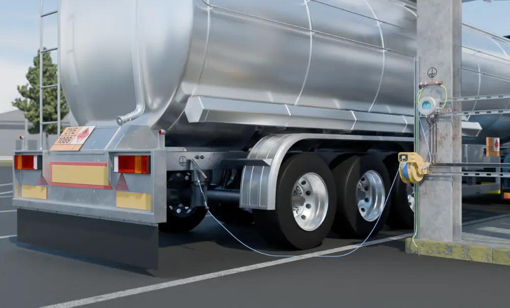
Grounding electrically conductive objects like road tankers, railcars, and drums prevents the accumulation of electrostatic charge by equalizing the object’s electrical potential with respect to earth.
Without grounding, static charge can accumulate on equipment like the ones listed during filling or mixing processes. This accumulation of charge can create a voltage rise that exceeds the breakdown voltage of the surrounding atmosphere, potentially leading to a static discharge. If the discharge energy exceeds the minimum ignition energy (MIE) of a combustible atmosphere, ignition can occur.
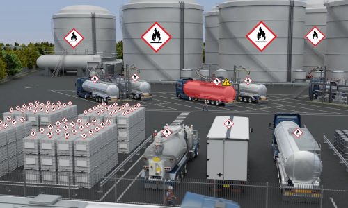
Uncontrolled static discharges pose a significant risk, especially in hazardous environments such as chemical plants, terminal tank farms, or grain silos where combustible atmospheres are present.
The buildup of static electricity is often overlooked, but its potential to cause catastrophic incidents cannot be understated. Addressing this risk is a critical step in helping to confirm the safety of personnel and infrastructure.
Electrical Resistance Benchmarks
The electrical resistance between the object being grounded and the earth is a critical factor in static control.
- Industry Recommended Practice: Technical specifications like IEC TS 60079-32-1* and NFPA 77** recommend a resistance of 10 ohms or less (R ≤ 10 Ω) to help confirm a reliable connection on metal objects and metal connections.
- Risks of Higher Resistance: Resistance above 10 ohms may indicate loose, corroded, or broken connections, which compromise safety. This can occur due to environmental factors such as corrosion, physical damage, or even improper installation.
- Testing and Maintenance: Grounding systems, including ground rods and interconnecting conductors, should be regularly tested to maintain low resistance throughout their service life. Testing should be documented to help confirm compliance with safety standards and provide a historical record of system performance.
When setting up static grounding systems, it is important to choose materials and components that are resistant to wear and environmental degradation. High-quality grounding clamps, for example, help to confirm a reliable connection and minimize maintenance requirements over time.
* IEC TS 60079-32-1 “Explosive Atmospheres, Electrostatic Hazards, Guidance”.
** NFPA 77 “Recommended Practice on Static Electricity”.
Visual Indication of Grounding Status
Operators often perform static grounding and bonding activities as part of their daily routines. Providing a visual reference ensures that grounding protocols are followed consistently.
- Visual Indicators: Green flashing LEDs are commonly used to signal a “good-to-go” status, indicating that the resistance is within the required limits (R ≤ 10 Ω).
- Continuous Circuit Monitoring: These indicators can show real-time resistance monitoring, helping operators detect loose or faulty connections before starting and during a process.
In high-risk environments, visual feedback systems should be supplemented with clear signage and operator training to help confirm procedures are followed correctly. Helping to confirm operators have the tools and knowledge to troubleshoot grounding issues helps maintain compliance with safety protocols.
Best Practice: Encourage a “Clamp On First, Clamp Off Last” procedure with visual cues to verify a secure ground connection before starting and after completing operations.
Adding Interlocks for Enhanced Safety and Control
Grounding systems with interlock contacts provide an additional layer of safety by integrating with equipment controls.
- Interlock Functionality: Systems with voltfree/dry or intrinsically safe contacts can signal pumps or PLCs to halt operations unless grounding requirements (e.g., R ≤ 10 Ω) are met. This prevents operators from accidentally starting processes without proper grounding in place.
- Supporting site SOPs: These systems enforce compliance with grounding SOPs, helping to confirm processes cannot begin without a verified ground connection. In the event of a grounding failure during a process, interlocks can automatically shut down equipment to mitigate hazardous conditions.
Using interlocks also reduces the reliance on human intervention, providing a mechanism that enhances overall system reliability. This helps automate safety measures and reduce reliance on manual checks.
Certification and Installation
Certification: Ensure that static control equipment complies with hazardous area classifications (e.g., ATEX/IECEx or Class and Division in North America). Only use systems certified by a third party for the specific hazardous area classification where they will be installed. Proper certification ensures that the equipment has been tested to meet the specific safety and environmental challenges of hazardous areas.
Proper Installation: Follow the manufacturer’s instructions to the letter, as improper installation can void certifications. Ensure installers have the required competency to work in hazardous areas. Review the manufacturer’s manual thoroughly before starting installation. It is also critical to verify that all components, including wiring and clamps, are suitable for use in the classified area.
Installation procedures should also include post-installation testing to verify that the system meets the specified resistance benchmarks. Routine inspections and maintenance checks help to confirm continued compliance and operational safety.
Treat the instruction manual as a controlled document approved by certification bodies and consult it for all installations.
Operator Training
Trained operators are the first line of defence against ignition risks, helping to confirm safe and compliant operations, and play a crucial role in static grounding and bonding procedures. Proper training helps them understand the risks and responsibilities of controlling static electricity.
- Risk Awareness: Train operators to recognize the ignition risks posed by electrostatic discharges in daily operations.
- Equipment Use: Provide hands-on training on the correct use of static control systems. Simulated training exercises can help operators practice responding to potential failures or alarms.
- Reinforce SOPs: Embed the “Clamp On First, Clamp Off Last” principle into grounding procedures. Ensure these procedures are clearly documented and readily available at all workstations.
By fostering a culture of safety and awareness, operators can become proactive in identifying and mitigating risks associated with static electricity.
Conclusion
Implementing effective static control solutions requires careful consideration of grounding resistance, visual monitoring, interlock systems, and proper installation.
By adhering to industry standards, performing regular maintenance, and investing in operator training, sites can significantly reduce the risk of ignition hazards caused by electrostatic discharges.
Incorporating advanced monitoring systems, automation, and a culture of safety ensures that facilities remain compliant and secure.
A comprehensive approach not only protects personnel and assets but also promotes long-term operational efficiency.