


When a high resistivity liquid, gas, or powder becomes electrostatically charged during process operations, it could charge electrically isolated conductive plant, equipment, and materials that are in direct contact with it, or in close proximity to it.
It is scenarios where the hidden increase in the voltage of the charged object presents the static ignition risk. This is because static sparks are caused by the rapid ionisation of the atmosphere between the charged object and objects that are at a lower voltage.

When the voltage of the object hits a critical level that exceeds the breakdown voltage of the medium present in the gap between the charged object, C1, and uncharged object, C2, ionisation occurs, which presents a conductive path for the charges to pass through the gap in the form of a spark.
The total energy available for discharge is based on the voltage (V) of the object and its capacitance (C), based on the formula shown below:


Table 2a: List of flammable liquids and gases and their
corresponding Minimum Ignition Energies
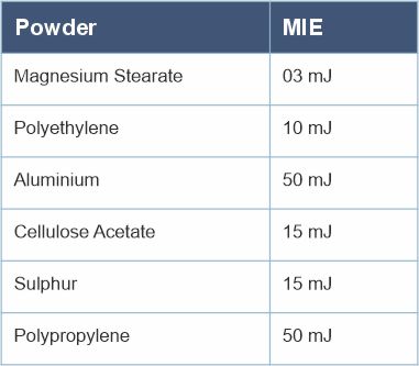
Table 2b: List of combustible powders and their corresponding Minimum Ignition Energies
As described in
Connections to the mass of the earth should be provided by high-integrity earth grounds present on the site. These high-integrity earth grounds will normally provide paths to earth for lightning and electrical fault currents and should be suitable for dissipating static electricity (ref: NFPA 77, 7.4.1.3.1).
The performance and condition of high-integrity earthing points are the responsibility of the site owner and need to be verified on a regular basis by a site-appointed competent electrical person.
Tables 2a and 2b detail MIE of some common liquids and powders used in process industries. If an object becomes isolated and the static voltage increases on it, then the charge on the object can quickly achieve a value above the product MIE and therefore be capable of igniting these flammable materials.
But what can cause equipment to become isolated? Tables 3a and 3b provide examples of equipment that can become isolated and the reasons for it.

Table 3a: Examples of Capacitance IEC TS 60079-32-1: Table A.2
NFPA 77: Table A.3.3.5
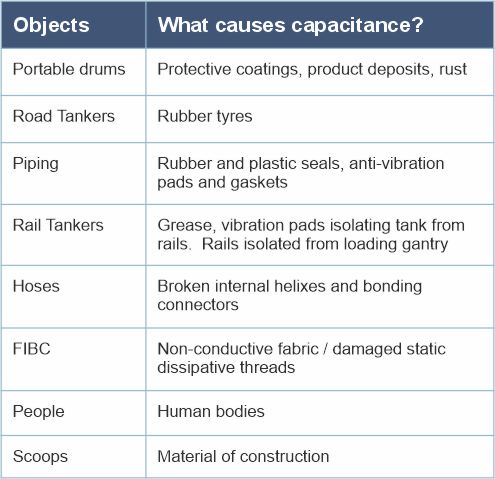
Table 3b: Equipment at risk of static charge accumulation and what can cause electrical isolation
Operator training is essential and should not be overlooked. Operators working in Ex areas should be trained on the basics of static electricity as a potential ignition source, as they are, ultimately, the day-to-day users of the earthing and bonding equipment that has been specified and installed at the site.
They should be trained on the intended function and correct use of the earthing equipment, and where the use of the earthing equipment fits within the standard operating procedures of the company. As a basic minimum for most application scenarios (e.g., earthing a metal drum), they should follow the principle of making earthing connections as the first step in the process and not remove the earth connection until the process is complete.
Operators should be trained to avoid scenarios where, for example, if earthing systems interlocked with the process have their earthing connections removed during the process, thereby initiating an emergency shutdown of the process (e.g., switching off a pump), there could still be movement of material after the machine has stopped, thereby carrying the risk of continued static charge generation.

If operators notice that equipment has been changed or damaged (e.g., fraying cable connections), they should be encouraged to report this to the relevant person at the location (line manager, local QSHE, maintenance personnel) and not use the equipment until a competent person has deemed the equipment safe and appropriate for use.
Not providing training risks incorrect use of the earthing equipment and/or not following the company standard operating procedures with respect to static electricity controls.