Newson Gale Ltd

Controlling the risk of electrostatic ignitions in chemical operations

Electrostatic Ignition Risks in Chemical Processing: Take Control

This article is designed to aid engineers, operations managers and safety professionals in understanding the root causes of static electricity and why it can be a potential ignition source in daily operations. The article will also provide a general overview of legislation and industry guidance relevant to static electricity and then outline practical methods around how it can be managed.

High levels of safety awareness in the intermediate and speciality chemical industry have been in place for decades, and the management and mitigation of electrostatic ignition source risk have always been a major practice for safety professionals, operations managers and engineers.

FM approved earthing clamps with rugged sharpened teeth are more likely to penetrate coatings and achieve effective earthing of equipment than basic clips and clamps.

1. Static as an ignition source​

Static electricity is just one of several sources of ignition regularly identified as being responsible for the ignition of combustible atmospheres (gas and/or dust), and there are a range of site-wide operations that can result in the generation of static electricity. Whether the operation involves filling, dispensing flammables or conveying/tipping powders into vessels, static electricity can be generated just through the movement of the material being processed or handled.

Because static electricity has long been known to present an ignition source in hazardous area operations, it is highlighted in legislation.

In Annex II of the ATEX Directive 2014/34/EU, it states the following:

Section 1.3.2 “Hazards arising from static electricity”

  • “Electrostatic charges capable of resulting in dangerous discharges must be prevented by means of appropriate measures.”

In carrying out the obligations laid down in Articles 6 and 9 of Directive 89/391/EEC, the employer shall assess the specific risks arising from explosive atmospheres, taking account at least of:

  • “the likelihood that explosive atmospheres will occur and their persistence,
  • the likelihood that ignition sources, including electrostatic discharges, will be present and become active and effective,
  • the installations, substances used, processes, and their possible  interactions,
  • the scale of the anticipated effects.”

Explosion risks shall be assessed overall.

Electrostatic Ignition Risk: Static spark

2. Getting to grips with static electricity

Although it is easy to understand why static electricity can be perceived as a mysterious topic to get to grips with, the principles around which static electricity can present an ignition source risk are relatively straightforward.

One common denominator is the interaction of electrically insulating materials (materials that have a low conductivity, e.g. toluene) with electrically conductive materials (e.g. plant equipment constructed from metals).

When an insulating material like toluene comes into contact with metal plant equipment, whether it’s flowing in piping, through a filter or being deposited into a drum, the toluene attracts electrons from the metal surface of the equipment it is in dynamic contact with.

The net result of this interaction is that the toluene is rapidly building a negative electrical charge, as it is attracting negatively charged electrons from the conductive metal, while the metal equipment is rapidly building a positive electrical charge.

Table 1 – Examples of static accumulating materials
Table 1: Examples of static accumulating materials

The problem with this situation, if it is allowed to continue, is that the voltage of both materials will rise rapidly if both materials are “isolated” from the earth.

Any object isolated from the earth can be described as possessing an “electrical capacitance”, which is denoted with the symbol “C” and is measured in Farads.

If we take the example of the toluene building a continuous negative charge as it flows through the metal piping system and gets deposited into an object like a metal drum, which, in this example, is isolated from earth, the drum will build a negative charge on its outside surface. The reason for this is that the negative voltage of the toluene forces the electrons in the drum to the outside surface of the drum. This is caused by the “rule-of-thumb” principle that like charges repel and unlike charges attract.

The problem with this scenario is that the voltage of the drum will rise based on the amount of negative charge residing on its outer surface relative to its own value of capacitance.

as09-drum-charge
Negative electrical charges distributed on external surface

The more charge, the higher the voltage. This scenario can be best explained through the formula:

(Source: NFPA 77: 6.3.1)

As more charge is deposited on the isolated object, there is a constant voltage rise. In our example, this is the outside surface of the drum as it is being filled with toluene.

Table 2_Capacitance of objects routinely used in the movement and containment of hazardous products

Table 2: Capacitance of objects routinely used in the movement and containment of hazardous products. (Source: IEC TS 60079-32-1  “Explosive atmospheres, Part 32-1: Electrostatic hazards, guidance” – Table A.2)

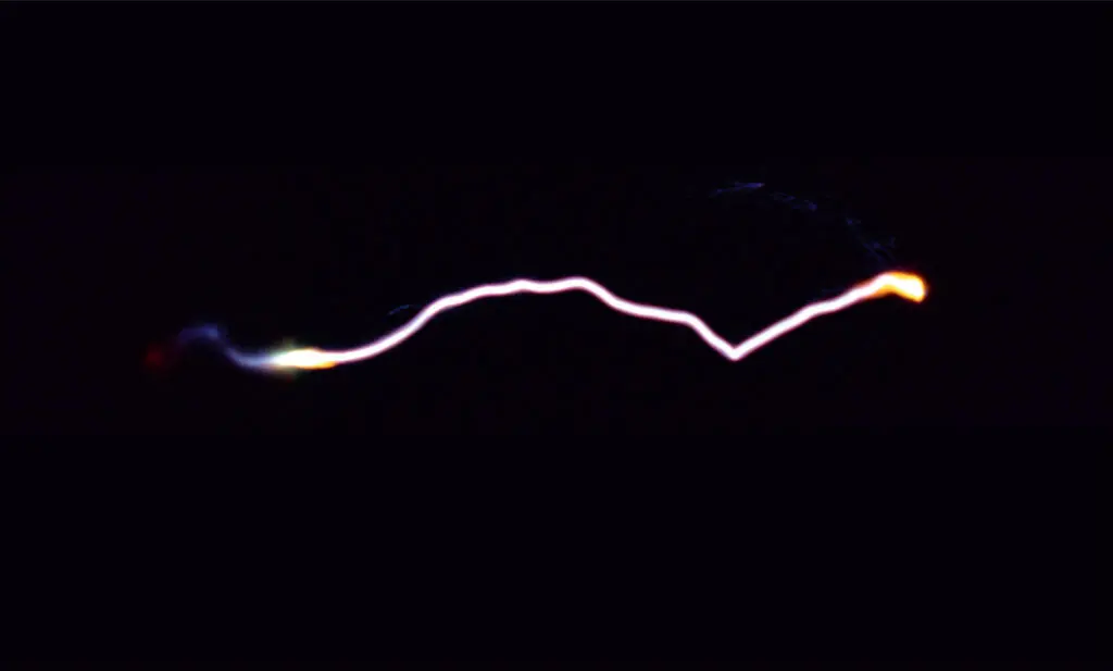
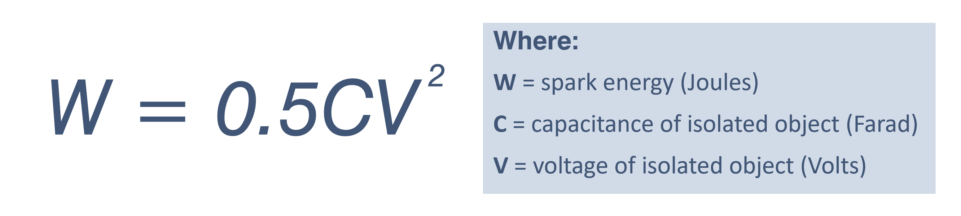
As the voltage rapidly rises and the electrical field strength around the surface of the drum passes 3000 volts per millimetre (the breakdown voltage of air at ambient conditions), there is a real risk that an electrostatic spark will be discharged from the surface of the drum into the potentially combustible atmosphere. In order to initiate combustion of the atmosphere, assuming it is within its ignitable range, the energy of the resulting spark must exceed the Minimum Ignition Energy (MIE) of the surrounding flammable atmosphere.

The potential energy of an electrostatic spark discharge can be illustrated in the formula:

(Source: NFPA 77: 6.9.1)

If it is assumed that the voltage of the object has exceeded the breakdown voltage of the surrounding atmosphere and is charged to a voltage of, say, 10,000 volts at the moment when there is a spark discharge to another object in close proximity to the drum, the potential energy of the resulting spark would be approximately 2.5 mJ. This assumes the drum has a minimum capacitance of 50 pF as indicated in Table 2.

If we are assuming that the flammable mixture surrounding the drum is a toluene-air vapour the minimum ignition energy would be in the region of 0.24 mJ (source: Table B1 of NFPA 77 “Recommended Practice on Static Electricity” (2024)), then the resulting energy from the spark would be capable of initiating combustion of the vapour.

Charge generation is not just limited to liquids. Powder processing operations can produce electrostatic charging rates well in excess of liquids and gases.

3. Processes capable of generating static electricity

In the intermediate and speciality chemicals sector, there are many processes that can result in the generation of static electricity as a natural by-product of the process in question. Such examples include, but are not limited to:

Road Tankers
Bulk material transfer
Type C FIBC Bags
FIBC Type C bag powder filling
Charge build up on powders

Table 3: Charge build-up on powders through different processing techniques and the quantity of charge typically carried per kilogram of powder. (Source: CLC/TR 60079-32-1 “Explosive atmospheres, Part 32-1: Electrostatic hazards, guidance” – Table A.1)

However, the vast majority of these situations can be managed by ensuring the objects at risk of static charge accumulation are not isolated from the earth. Because fixed plant, like large storage tanks and vessels, should be earthed via the plant structure, the risk of static spark discharges is most pronounced for movable objects ranging from road tankers to people.

Table 4 highlights some of the sources of electrical isolation on movable equipment. If the objects are connected to earth, then the charge imbalance on the object is neutralised, which mitigates the risk of a static spark with enough energy to ignite potentially combustible atmospheres.

Examples of why process equipment and people can be isolated from earth
Table 4: Examples of why process equipment and people can be isolated from earth
Testing: Sole-Mate insulating footwear tester
Sole-MateTM static dissipative footwear testing
“True Earth Ground” - a connection to the general mass of the earth that has been measured and verified to be below 10 ohms

4. Earthing and bonding systems

Earthing potentially isolated equipment should be regarded as a compulsory safety function in any process and area where combustible products are handled and processed. It is the most practical and effective way of mitigating the accumulation of static electricity on equipment (and people). However, having objects in contact with the earth is not earthing. For example, resting a drum on concrete or using drag chains on road tankers does not provide an effective and reliable means of preventing static charge accumulation.

So what does “earthing” (or “grounding”) really mean? In effect, if we can connect our potentially isolated equipment to a verified “true earth ground” i.e. a connection to the general mass of the earth that has been measured and verified to be below 10 ohms, in accordance with a standard like the EN 62305 standard for earthing lightning protection systems, we can be confident that connecting to installed earth networks like the local lightning and electrical earthing protection system will enable static charges dissipate safely from the process equipment. The bus-bar network that feeds out from the earth rods (installed earth network) can provide a means of earthing our process equipment.

Bonding is different to earthing in that it ensures that two bonded objects at risk of static charge accumulation are at the same electrical potential, however, it does not mean they have no charge, i.e. are at earth potential (0 volts). Bonding ensures there is no risk of static spark discharges between the bonded objects. It does not mean they are not capable of discharging sparks to objects at a lower electrical potential.

For movable metal objects, this extract from IEC TS 60079-32-1 “Explosive atmospheres, Electrostatic hazards, guidance” recommends the following:

Section 13.4 “The establishment and monitoring of earthing systems”

13.4.1 Design

“Permanent bonding or earthing connections should be made in a way to provide low resistance during its lifetime, e.g. by brazing or welding. Temporary connections can be made using bolts, pressure-type earth clamps, or other special clamps. Pressure-type clamps should have sufficient pressure to penetrate any protective coating, rust, or spilled material to ensure contact with the base metal with an interface resistance of less than 10 Ω.”

A resistance of 10 ohms or less refers to the resistance between the object requiring static earthing protection and the local earth network.

Any resistance higher than this value would indicate loose connections or corrosion (see NFPA 77 ref. below), which could limit the dissipation of electrostatic charges from the equipment undergoing electrification. The challenge, however, is to ensure we implement a consistent and reliable means of connecting to these networks, especially since most of the equipment we are dealing with is portable and will not have a permanent connection to the site’s local earth network.

NFPA 77, Section 7.4.1.3.1 (2019 ed), “Recommended Practice on Static Electricity”

“Where the bonding/grounding system is all metal, resistance in continuous ground paths typically is less than 10 Ohms. Such systems include those having multiple components. Greater resistance usually indicates that the metal path is not continuous, usually because of loose connections or corrosion. A permanent or fixed grounding system that is acceptable for power circuits or for lightning protection is more than adequate for a static electricity grounding system.”

5. Implementing practical earthing solutions

The implementation of a consistent and repeatable way of earthing mobile equipment needs to take into account the characteristics of the process, who the responsible people are for performing the earthing and bonding safety function on a daily basis, and other factors like environmental conditions and the classification of the hazardous area. 

Whatever method is adopted, it is critical to ensure that the person (people) responsible for performing the safety function of earthing equipment understand the importance of doing it and that the earthing activity itself is kept relatively simple.

There are many cases where sites with good earthing practices have been caught out, either due to forgetfulness on the part of an operator or because a minor flaw in the process has been missed.

6. Industrial grade earthing clamps

Earthing clamps are the most “traditional” means of connecting mobile plant equipment to verified earthing points. However, equipment specifiers need to be aware of the difference between clamps like alligator clips as compared with static earthing clamps that have been designed for repeated use in harsh industrial environments.

Clamps, like alligator clips, are designed to be attached to clean surfaces like battery terminals. They are not designed to penetrate industrial-grade protective coatings or product deposits on equipment that would otherwise not permit static charges to pass through them. So even though the clamp may be attached to the object, it does not mean it is effectively earthing it.

Clamps that combine a strong spring pressure with sharp, rugged teeth have a greater chance of penetrating surfaces that would otherwise prevent a reliable electrical and mechanical connection to the equipment undergoing electrification by electrostatic charging.

Clamps that carry the FM approval mark will have passed a range of functional tests that demonstrate key functional performance characteristics to operate successfully. 

Although the use of a basic earthing clamp will not verify a low resistance connection to equipment for the operator, selecting an earthing clamp that combines FM approval with a set of sharp teeth capable of penetrating layers that would otherwise inhibit static charge transfer will enhance the likelihood of repeatable and reliable earth connections to plant equipment.

Bond-Rite® earth circuit monitoring units

7. Verifying a positive earth connection

Combining certified earthing clamps with an earth monitoring system adds the benefit of providing positive confirmation to operators that a 10 ohm or less connection to the plant equipment requiring static earthing protection has been achieved after they have attached the earthing clamp.  

This effectively removes the “guesswork” out of knowing whether or not the equipment is earthed. Once a connection of 10 ohms or less has been verified by the system, an indicator like a flashing green LED will let the operator know that they can proceed with the operation (e.g., filling or mixing operation).

The benefit of the flashing green LED principle is that it lets people in the area know that the system is continuously monitoring the health and effectiveness of the earthing circuit and that should the resistance rise above 10 ohms, or the clamp’s connection to the equipment be compromised in any way, the LED will switch off.

This will notify people working in the area that the process should be halted, or if it cannot be halted, that the equipment should not be approached until an adequate charge relaxation time period has been adhered to after the process has finished.

The use of an earth circuit monitoring system with an indicator has the added benefit of becoming a core step in the operator’s Standard Operating Procedures (SOP), so that if the green light is not obtained, the process should not begin.

It also enhances the site’s ability to demonstrate compliance with the recommendations of IEC TS 60079-32-1 and NFPA 77 by ensuring the process does not start unless a verified 10 ohm or less connection has been achieved.

Earth-Rite® RTR (left) and Earth-Rite® MULTIPOINT monitoring units with interlock capabilities.

8. Earth verification with interlocks

If the process that causes charge generation is automated, an alternative option is to specify an earthing system that will not only verify and indicate an earth connection resistance of 10 ohms or less but, through its volt-free contacts, control the process (e.g., road tanker loading operation).

Unless the earthing system detects a 10 ohm or less connection, it will not permit the process to begin.

It should be borne in mind that if the earthing system is interlocked with devices to control the flow/movement of material, although the device causing material movement (e.g., a pump) may have stopped (e.g., through accidental removal of the clamp mid-transfer), there could be a period of time before the flow or movement of material stops completely.

It is the responsibility of the customer to determine what measures need to be in place to manage scenarios where static charge could still be present. Likewise, if the clamp’s connection or the earthing circuit should be compromised during the process, the earthing system will automatically detect this situation and halt the process, thereby stopping the further generation and accumulation of static electricity on the process equipment.

The benefit of this type of system is that it really enforces the SOP of earthing the object prior to process initiation.

Again, what needs to be borne in mind is that the person tasked with ensuring the safety function of earthing the equipment is actioned via an easy and repeatable way of earthing the equipment.

The most effective way of getting acceptance and engagement from the operator is to keep the visual indication and mode of operation as simple as possible. A simple, solid red ‘NO-GO’ and a flashing green ‘GO’ method of indication is an effective concept for people to engage with.

This is in line with a simple action of connecting the earthing clamp to the object requiring earthing, without any additional need to interface with switches and dials, simplifying the procedure. Also, take a look at the level of control.