


For over 40 years, Newson Gale has been at the forefront of incorporating the static control measures of international associations, like International Electrotechnical Commission (IEC), CENELEC, and National Fire Protection Association (NFPA), and industry sector associations into the functional performance of its static grounding and bonding equipment.
While other manufacturers follow our lead or choose to incorporate arbitrary static control performance parameters into their solutions, Newson Gale has been, and continues to be, committed to providing our customers with hardware solutions that align with the control measures outlined in recommended practice in static grounding and bonding control product solutions.
Keep reading to find out more.

Product standards for equipment operating in Ex atmospheres
Regulations like the ATEX Equipment Directive (2014/34/EU) are aimed at providing workers and businesses with equipment that incorporate into their design equipment protection techniques which mitigate against the ignition of the surrounding Ex atmosphere if critical faults occur with the equipment, e.g., electrical sparks or arcs.
In countries that follow ATEX, UKCA, IECEx product certification and hazardous area zoning regulations, the equipment protection techniques that apply to equipment installed in Ex atmospheres can be found in the IEC EN BS 60079 “Explosive atmospheres” series of standards. To obtain a CE or UKCA mark, additional standards, like electromagnetic compatibility (RFI/EMC) and low voltage directive (LVD) must be complied with.
Grounding and bonding systems with active electronic monitoring circuits in Ex atmospheres also need to comply with such regulations. And although standards exist for the Ex certification of static grounding and bonding systems, there are no formal product standards that govern the performance parameters of such equipment when used in the context of static grounding and bonding functionality.
Technical specifications addressing the ignition hazards associated with static electricity
*CENELEC adopts the IEC TS 60079-32-1 Technical specification and publishes it as a “Technical Report”, which is listed as CLC/TR 60079-32-1 “EXPLOSIVE ATMOSPHERES – Part 32-1: Electrostatic hazards, guidance”.
“It gives the best available accepted state of the art guidance for the avoidance of hazards due to static electricity. This document is mainly written for designers and users of processes and equipment, manufacturers and test houses. It can also be used by suppliers of equipment (e.g. machines) and flooring or apparel when no product family or dedicated product standard exists or where the existing standard does not deal with electrostatic hazards.”


Incorporating Recommended Practice into grounding and bonding solutions
In the absence of specific product standards (other than Ex certification requirements), Newson Gale aligns, wherever possible, the performance parameters of its grounding and bonding solutions with the control measures specified in industry guidance documents.
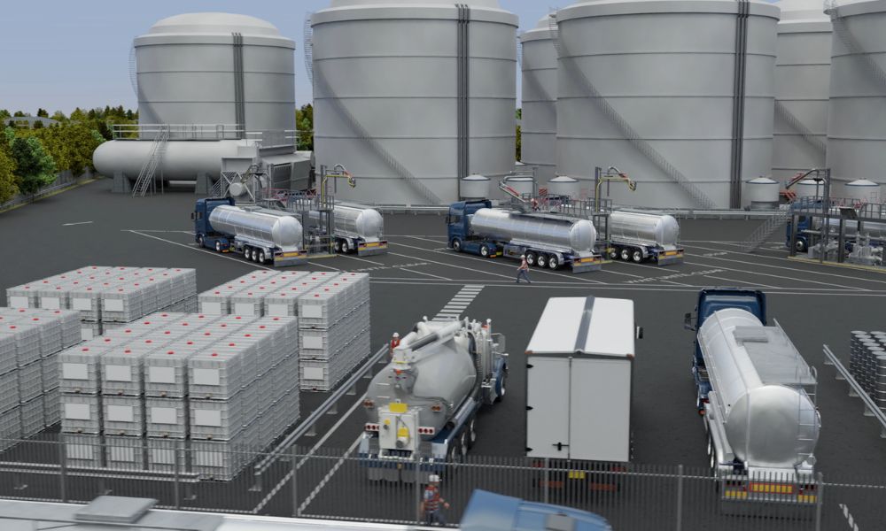
Equipment regularly used in industrial operations can be subjected to “heavy-duty treatment” by operators and the materials that are being handled or processed. In such environments, grounding and bonding solutions should be capable of establishing and maintaining a stable connection to the object that needs to be grounded for the period of time the process generating static charge is underway. Central to the operating parameters of any grounding or bonding solution is the electrical resistance present between the object and a plant verified earthing point. For the electrostatic charge to be transferred from the object to the verified grounding point, we need to know what the electrical resistance is between both points. This is what we normally refer to as the “ground loop”.

This ground loop encompasses the:
- Capability of the connection device (e.g., grounding clamp) to bite through connection inhibitors like paint, coatings, rust, grime build-up to the base metal of the object;
- The cable, and its connections, between the grounding clamp and the ground monitoring system;
- The ground path for static charges via the grounding system itself and finally;
- The ground loop connection(s) to the verified earthing point.
Why 10 ohms or less?
While a theoretical resistance to earth of 1 meg-ohm is generally considered as capable of dissipating static electricity, the current carrying value of the ground loop is not the primary concern for mitigating against the accumulation of static electricity. The primary concern is the physical integrity of the temporary or semi-permanent circuit that is made between the object that requires grounding and its connection to the verified earthing point.
The guidance listed above states that if there is a resistance in the circuit higher than 10 ohms it is likely that there are loose or corroded connections somewhere in the circuit. Scenarios like this should be addressed immediately as the channel for removal of the static charge could be impeded. Setting a benchmark self-monitoring resistance of 10 ohms or less provides early indication of such situations. Given that the objective of the grounding system is to mitigate against the accumulation of static electricity, accompanied by the risk of a potentially incendive static spark discharge, setting a benchmark resistance threshold of 10 ohms or less makes practical sense.
To actively monitor ground loop circuits to a benchmark threshold resistance of 10 ohms or less requires electronic monitoring systems that have a high degree of precision and repeatability. With the exception of the Earth-Rite® FIBC ground monitoring system, all Newson Gale products, with active ground loop monitoring circuits, incorporate a 10 ohms or less threshold resistance level.
What follows are examples of the control measures outlined in the
documents listed above.