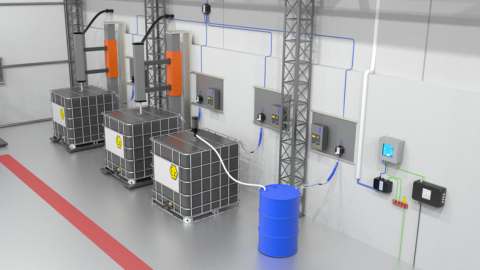


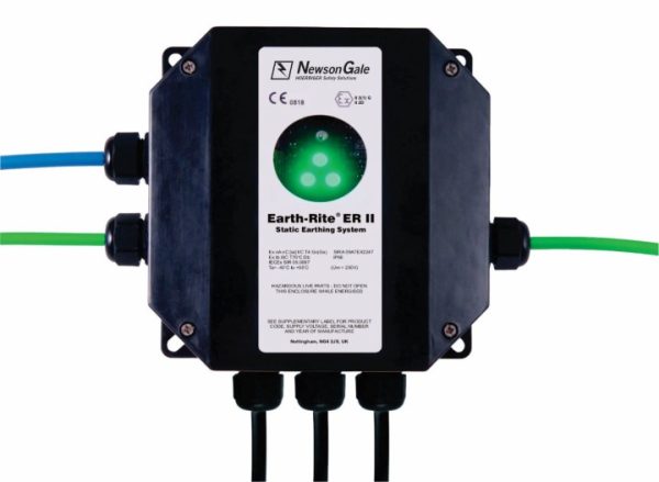
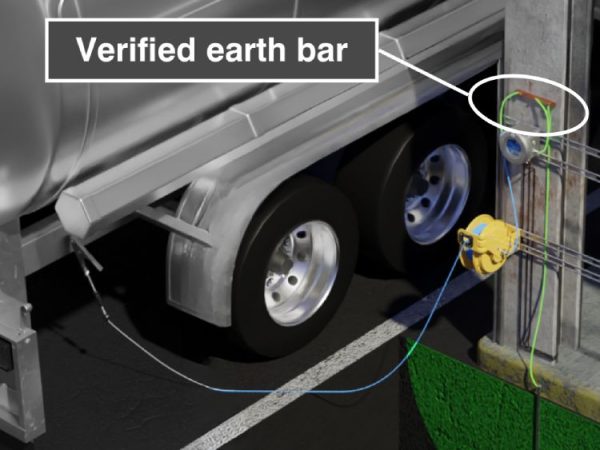
The earthing solution’s connection to the verified earthing bar is paramount to the safety of the system. Depending on the design of the intrinsically safe monitoring circuit, the connection will need either a high-integrity earth connection or a local verified earth connection. Utilising the design concept of galvanic isolation for the intrinsically safe circuit allows for the system to be installed to a local verified earth bar, often offering easier installation due to not having to install long cable lengths to a high-integrity earth.
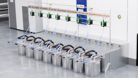
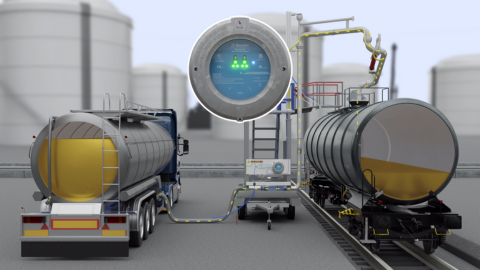
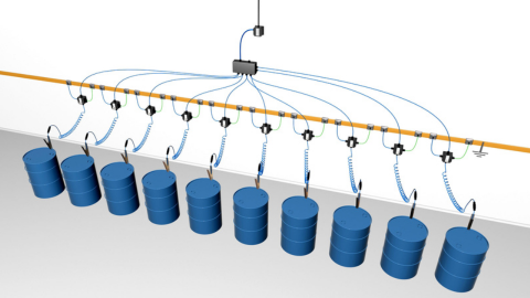
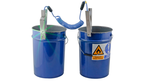
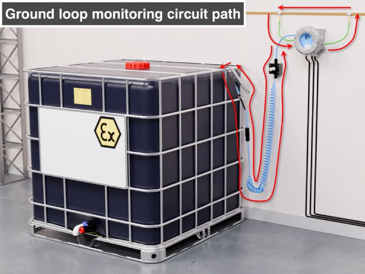
The connection to the verified earth bar should also be actively monitored to ensure the electrical resistance present between the object to be earthed and the verified earth connection provides a passage for static charges to earth. Having an earthing system that incorporates two connections to the verified earth bar allows the earthing system to continuously monitor the circuit through the earth bar during the process.
Should a rise in resistance over the earthing system’s maximum resistance parameter occur in these connections, either through loose connections or degradation over time, then the earthing system will not go permissive. This provides maintenance staff with an opportunity to investigate and identify the source of resistance (e.g. loose or broken connections) and rectify it to maintain the safety of the process.
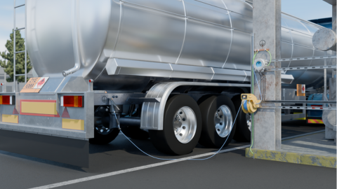
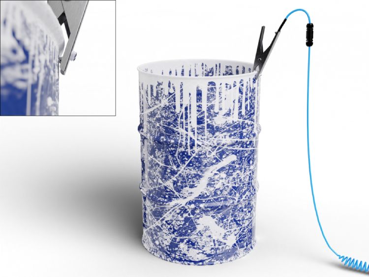
The primary source of electrical resistance in many applications will be the connection of the earthing clamp (or other connection method) to the object requiring static earthing. The operations of many industrial processes will very often result in equipment being covered in product deposits, thick protective coatings, rust or the build-up of dirt/grime over a sustained time period.
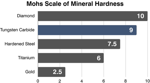
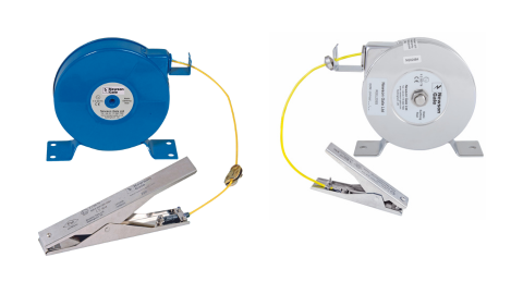
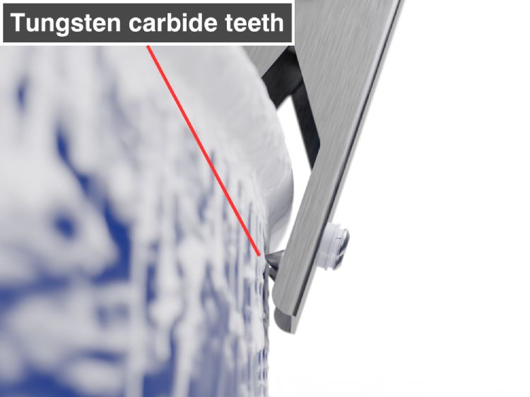
In order to achieve a 10 ohms or less connection it is crucial that the earthing clamp is capable of penetrating such layers in a repeatable, robust and reliable way. It is for this reason that Newson Gale pioneered the use of the hard-wearing metal tungsten carbide (table) to produce teeth capable of penetrating connection inhibitors like product deposits, paint coatings, rusted surfaces, etc.
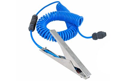
The sharpened profile of the teeth used in combination with a strong spring housed in a heavy-duty stainless steel body enables their repeated use in harsh industrial environments. Not only are strong initial connections made to the equipment, but they are also maintained for the duration of the material handling process.
Although the magnitude of electrical current generated by electrostatic charging can be relatively small, normally in the micro-amp range, the resulting voltages can be very high and well beyond the breakdown voltage of air. It is commonly quoted that a theoretical resistance of 1 meg-ohm to true earth will dissipate static electricity. However, due to the harsh industrial environments in which earthing equipment typically operates, and because most earthing applications require many repeated connections and disconnections to process equipment, the robustness and reliability of the earthing solution are the primary concern with respect to intended performance.
For that reason, independent bodies like the International Electrotechnical Commission (IEC) and National Fire Protection Association (NFPA) recommend resistance levels of 10 ohms or less between the object requiring static earthing and the verified earthing point. The reason for this is that resistances higher than 10 ohms in the circuit between the object and the verified earthing point indicate potential compromise of the earthing circuit, like a poor initial connection to the equipment via the earthing clamp, or loose/corroding connections that could otherwise prevent the passage of static charges to earth.
In addition to the publications highlighted above, an electrical resistance of 10 ohms has often been cited in industry specific guidelines and scientific journals as a good benchmark for indicating a reliable path to a verified earthing point. In the vast majority of application settings, the object requiring static earthing will be made of metal, as will the verified connections to earth.
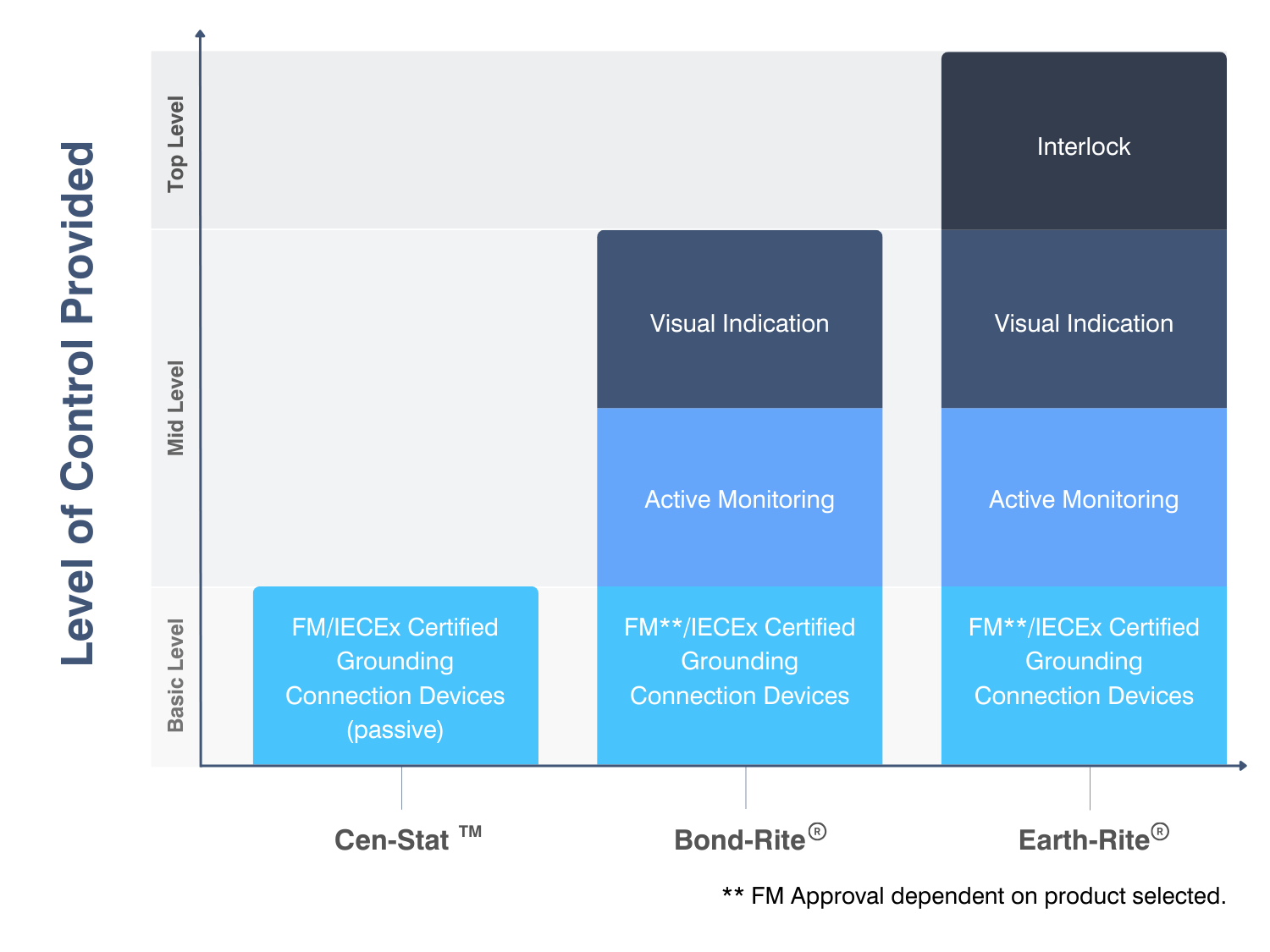
At the lower end of the scale is the option of specifying combinations of earthing clamps with cables or reels that provide none of the benefits listed above. In this case, we are describing “passive” earthing solutions where it is assumed that the connection between the object and the verified earthing point is performing the intended function of transmitting electrostatic charge to earth.
To compensate for the information gap provided to operators it would be prudent for competent electrical persons to test the electrical resistance of the connection of these installations with ohm meters (certified for use in EX atmospheres) on a regular basis to determine if there are breaks in electrical continuity that could otherwise impede the transfer of static charge to earth.
Additional certifications, (like FM approval), can provide a higher degree of confidence in the ability of the clamp to establish and maintain a secure connection to equipment but it will not completely compensate for the benefits provided by active solutions.