


Monitoring Unit & GRP PSU
Monitoring Unit - Zone 0/20 Installations
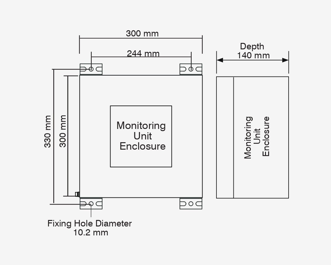
Power Supply Unit - Zone 2/21 Installations

Marshalling Junction Box

Remote Indicator Station Associated Apparatus - Zone 0/20 installation

Monitoring Unit & Stainless Steel PSU
Monitoring Unit - Zone 0/20 Installations
Power Supply Unit - Zone 2/21 Installations

Marshalling Junction Box

Remote Indicator Station Associated Apparatus - Zone 0/20 installation
Overview of the Earth-Rite® MULTIPOINT
Eight active earth monitoring circuits in one system
The Earth-Rite® MULTIPOINT is a single earthing system that provides site operators with eight independent active earth monitoring circuits that can be used to monitor the earth status of eight discrete pieces of equipment used in Ex atmospheres.
The monitoring unit consists of an array of eight pairs of green and red LEDs that indicate if the equipment is connected to a verified static earthing point.
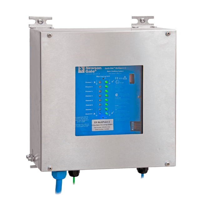
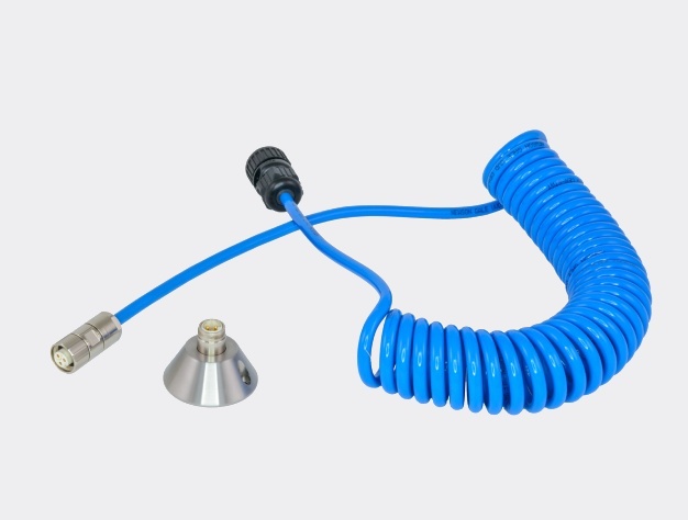
The monitoring unit utilises the highest level of intrinsically safe circuits Ex ia to allow for the connection to equipment in areas classified as Zone 0 or Zone 20 (covering all gas, vapour, and dust groups). This removes any doubt regarding the location or existence of a Zone 0 or Zone 20 atmosphere at the point(s) where the MULTIPOINT is connected to equipment. Temporary and semi-permanent connections can be made with a range of 2-core earthing clamps and connectors.
The monitoring circuit requires a resistance of 10 ohms or less before it will indicate a permissive condition to the operator supervising the procedure. A simple traffic light method of “GO/NO GO” red and green LED indication provides process operators with a simple means of knowing that they can continue with the next step in their process procedures.
10 ohms is a benchmark resistance threshold defined in multiple best practice industry guidelines for the control of static electricity in Ex atmospheres. If the output contact driven by the corresponding monitoring circuit is active, and the earth status condition is permissive, a volt-free SPDT relay will be energised.

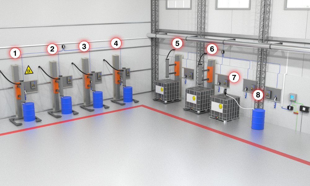
The monitoring unit is connected to equipment in the Ex area via marshalling boxes that route the monitoring circuits to the points at which the system will be connected to the equipment requiring static earthing.
If the equipment is in a position where it is difficult for operators to see the main LED array on the face of the monitoring unit, additional remote indicator stations mounted at the point of connection can be specified.

The remote indicator stations, fitted with a pair of red and green LED indicators, can be mounted in Zone 0 or Zone 20 locations. The LEDs are powered by intrinsically safe Ex ia circuits, with their enclosures classified as simple apparatus.
When the MULTIPOINT detects a connection resistance of 10 ohms or less to the equipment, the LEDs on the remote indicator station switch from red to flashing green. The flashing effect demonstrates that the MULTIPOINT is continuously monitoring the earth circuit for the equipment requiring electrostatic earthing.
The channels for each monitoring circuit can be activated or deactivated via a set of DIP switches located on the front panel inside the monitoring unit.
Multiple interlocking combinations
Specification support
Reliability

UKCA Certificates - United Kingdom

ATEX Certificates - Europe

IECEx Certificates - International

cCSAus Certificates - United States

CCC Certificates - China

KCs Certificates - South Korea


Book a live product demo
Newson Gale has an extensive product range that can be tailored to your processes and the range of hazardous area classifications at your location. The most effective way to identify what is applicable for your operations is by talking to our team. They will provide in-depth information on the products, features and how the range of options can be tailored to your needs.
